Start a New Design
To start a new design, you can do it in one of below three ways:
Start from GUI
Start from .link file
Start from .cmd file
Whichever way you choose, you always follow below steps to go:
Load in IP modules (Component)
Instantiation of IP modules (leaf module)
Create leaf module container (shell module)
Build design hierarchy
Create ports of top-level module
Save into .link file
LINK file is the main data file used by LinkFab, however user can manually modify it sometimes. Read chapter LINK File for more information about LINK file syntax.
Start From GUI
It’s the easiest way to start with GUI, run below command to enter GUI mode:
$> qk linkfab -g
- Step-1: Load in IP modules
Select menu Design->Load Entity, or shortcut:
CTRL-l; The Load Entity dialog will popup, as below: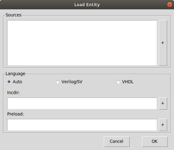
Click on “+” button of sources part, user can select the IP module files, multiple files can be selected at one time.
LinkFab can recoginize file language by file extension, for example, .v, .sv as Verilog file, .vhd, .vhdl as VHDL file; Otherwise user need to choose the correct language in the language choices;
For Verilog files, if there is “`include” directives in the file, the include file need to be found and parsed; The include file locations need to be specified, clicking “+” button of incdir part enables user to select include directories, multiple directories can be selected; But if the include file is in the same directory as the module file, no need to set incdir, LinkFab will search the module file directory as default for the included files;
For some Verilog files, some variables are used, while variables are defined in other header file, which is not specified by `include directories; In this situation, incdir can not solve this issue, however preload can solve it; Click on “+” button of preload part, user can make LinkFab parse some preloading files before a module file is parsed; Multiple preloading files can be selected;
By clicking “OK” button, LinkFab will load in all the IP moduels into Component window;
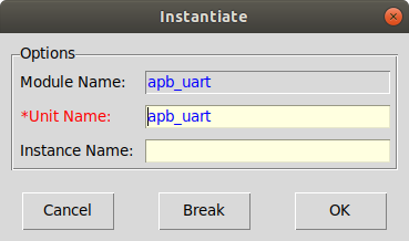
- Step-2: Instantiation of IP modules
After load in IP modules, they need to be instantiated; At the Component page, selecte the modules, and right-click to popup the menu, select menu-item “instantiate”, then LinkFab popup the instantiate form, you need to fill the unit-name and instance-name, if the instance-name is same with unit-name, it can be left empty;
By clicking “OK” button, IP module is instantiated into Hierarchy page. When multiple modules are selected to instantiate, the instantiate form will popup again for the next module to be instantiated, if you want to cancel the following instantiation, click “Break” to exit this operation.
- Step-3: Create shell modules
After all IP modules are instantiated, shell modules need to be created to build hierarchy;
Select menu: Design->Shell Module, the Shell Module form will popup, user need to fill the unit-name, module-name, instance-name; If module-name, instance-name are same with unit-name, they can be left empty;
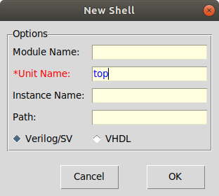
Note
Shell module has the same icon color with leaf module when it’s created initially, and after it has child module, it will change the icon to yellow one.
- Step-3: Build design hierarchy
Hierarchy building is very simple, go to the Hierarchy page, and just use mouse to drag & drop;
Click on one leaf module, move it over a shell module, and then drop it directly when the shell module’s icon is yellow;
Hint
When the leaf module is the first child module of the shell module, drop it directly will has no effect, user need to press down CTRL key and then drop it. This is to avoid the wrong operation to move a leaf module under a leaf module.
- Step-4: Create ports of top-level module
There are 2 ways to create ports of top-level module:
Create port on Component page, and then synchronize to the instance module on Hierarchy page
Map instance module’s port directly to the top-level module
- Create on Component page
Go to Component page, select the shell module’s component, in the bottom of Content pane you will see Node properties, there is New button in orange color, clicking on New button will create a new port of the selected module, with name of “NewNode_nnn”, you can change this name and press RETURN, for other port properties, you can change them too;
After creating all the componet ports, go to Hierarchy page, select the shell module, whose componet just added some ports, then right-click to popup the menu, select the Sync with entity item, LinkFab will copy all the new created componet ports to the shell module.
- Map instance module port
Go to Hierarchy page, select the shell module, then select the port which need to map to top-level module, right-click to popup the menu, select map2top item. Then LinkFab will check whether the port on top-level module exists or not, if not exists, create it firstly, and then connect them;
Hint
Actually, create ports of any shell module is the same.
- Step-5: Save design
When you load in all IP modules and instantiate them and build the design hierarchy, now you have a good initial state of an integration design; You can save the design into a .link file, and it will contain all the information you just made in above steps; The .link file can be loaded in a future time, to continue the integration job;
To save the design, select menu: File->Save, if it is not saved before, the window title is showing (untitled), and a Save dialog will popup, you can type in a filename, and click OK to save it; After saving, the window title will change to the saved filename.
The shortcut:
CTRL-sis to save the design.
Start From LINK File
LINK file is the main data file of LinkFab, user can edit this file directly, it has the same effect as GUI does; For detail information of LINK file, read the chapter LINK File;
Step-1: To load in IP modules, write below code:
instance modA \
    module      <module-name> \
    instname    <instance-name> \
    path        <module-path> \
    incdir      <include-directory> \
    preload     <preloading files>

generic param1 value1
generic param2 value2
If there is no parameters, the line of generic can be skipped;
Note
The generic line has to follow the related instance command, since it’s a separate command, so there is no “\” at the end of instance command.
This command will load in IP module, and at the same time, instantiation is also done; So user dosen’t need to instantiate the module;
In this example, modA is the unit name for LinkFab usage, <module-name> is the module’s name in the source code, <instance-name> is the instance’s name in generated code, <module-path> is the directory where module file is located, incdir can be skipped if there is no `include directives in module file, preload can be skipped if there is no variables used when variables are defined in another header file while no `inlcude directives used;
Step-2: To create shell module, write below code:
generate verilog shellA \
    module      <module-name> \
    instname    <instance-name> \
    path        <module-path> \
This command is similar to instance command, since shell module will be generated, so no need for information of incdir or preload, or even generic command;
To generate VHDL code, replace verilog keyword with vhdl;
Step-3: To build hierarchy, write below code:
hierarchy shellA = shellB modA modB \
                   modC modD

hierarchy shellB = modE modF
Command hierarchy specify a shell module’s child modules, all shell modules and leaf modules are defined in above 2 steps;
Step-4: To create ports of top-level module, write below code:
pin input   shellA.portA
bus output  shellA.portB(31:0)
pin inout   shellA.portC
Keyword pin and bus are used for single port and vector port, and port IO can be set by keyword input, output, inout;
Since .link file is the data file, so saving this file is saving the design;
To continue with the connection job, run LinkFab GUI and click the menu: File->open to open this .link file, you will see the loaded components and design hierarchy.
Start From Command File
The .cmd file can be used to create a new design too; There are many commands supported, but for a design start, only a few command can make this task done; Please refer to Command Reference for detail information;
Step-1: Load in IP modules:
instance modA module <module-name> inst <instance-name> incdir <include-directory> file <module-file>
Keyword module is for Verilog file, and entity is for VHDL file; Keyword inst is for instance name, if it has same name with unit-name modA, then it can be skipped; Keyword incdir is for verilog file whose has “`include” directives in its code, and the include file is not in the same directory with module file, more directories can be separted by comma;
Step-2: Create shell modules:
instance shellA module <module-name> path <module-path>
Create shell module has same command with loading in IP modules, but has no file attribute;
Step-3: Build design hierarchy:
hierarchy shellA = modA modB
Step-4: Create ports of top-level module:
add node shellA.portA               # create a single port
add node shellA.portB(31:0)         # create a bus port
This command only create shell module ports, for leaf module, it has no effect;
Step-5: Save design:
save a.link
The saved data file a.link can be loaded in future, either by GUI or by command, for further processing;